
Xinping Xinping

Why Use a Common Mode Choke?

Time:2026-09-19 Author:Henry
0%

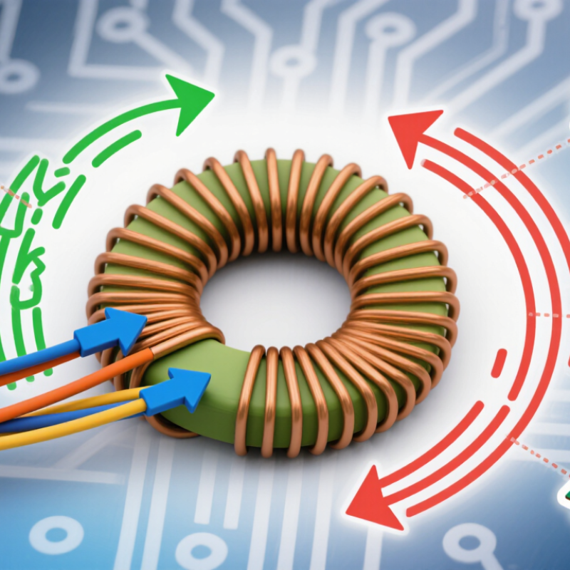
Modern electronic equipment often fails quietly before it fails visibly. A motor starts, a switching converter changes load, and unwanted noise travels along connected cables. This interference can disturb sensors, communication lines, audio circuits, or nearby equipment. A Common Mode Choke helps reduce this problem by opposing common-mode noise while allowing useful differential current to pass. Its windings carry the desired current in opposite magnetic directions. Their normal fields largely cancel. Noise flowing in the same direction strengthens the magnetic field, creating impedance against that disturbance.

The component is useful in power supplies, USB interfaces, industrial controllers, LED drivers, and automotive electronics. Its value becomes clearer during testing. A prototype may work on the bench, then fail an electromagnetic compatibility check after a longer cable is attached. Adding a suitable choke near the noise source can reduce radiated and conducted emissions. Placement matters. So does frequency.

It is not a magic filter. Poor winding selection, saturation, parasitic capacitance, and incorrect impedance can weaken performance. A choke designed for low-frequency power may perform poorly against fast switching edges. Engineers should review rated current, leakage inductance, insulation requirements, temperature rise, and impedance curves. Measurements with current probes and spectrum analyzers provide stronger evidence than assumptions. That evidence may still be incomplete.

Real designs involve compromises. More filtering can increase size, cost, or signal loss. The best solution depends on the noise path, operating current, circuit topology, and compliance target. Understanding these limits explains why engineers use a Common Mode Choke—and when another filtering method may be more appropriate.
Why Use a Common Mode Choke?

What Is a Common-Mode Choke? Two Windings on One Magnetic Core

Why Use a Common Mode Choke?

A common-mode choke uses two windings on one magnetic core. Each winding carries one conductor, such as line and neutral. The desired current flows in opposite directions. Its magnetic fields largely cancel. Common-mode noise travels in the same direction on both conductors. Those fields add inside the core, creating high impedance against unwanted interference.

This arrangement is compact, passive, and practical. It can reduce conducted emissions before they reach a cable or enter sensitive circuitry. On a bench, engineers often inspect the choke beside an oscilloscope and a noise analyzer. Small winding differences still matter. Imperfect symmetry can create differential-mode effects, which designers may overlook. The component is not a magic shield.

Selection depends on rated current, inductance, core material, leakage inductance, and impedance across frequency. A choke that performs well at 150 kHz may behave differently near 30 MHz. Test conditions matter. IEC 61000-4-6 places conducted immunity testing across 150 kHz to 80 MHz, showing why frequency response cannot be judged from one datasheet value. The Global E-waste Monitor 2024 reports 62 million tonnes of electronic waste generated in 2022, with the figure expected to reach 82 million tonnes by 2030. More connected equipment increases the need for reliable electromagnetic compatibility. Still, layout, grounding, enclosure design, and cable routing can defeat a well-selected choke. That is the part engineers sometimes learn too late.

How Does It Work? Common-Mode Rejection Versus Differential-Mode Current

Why Use a Common Mode Choke?

A common mode choke targets unwanted current flowing in the same direction on paired conductors. Its windings share one magnetic core. Common mode currents reinforce magnetic flux, creating high impedance. Differential mode currents flow in opposite directions, so their flux largely cancels. The intended signal therefore passes with limited disturbance. That distinction matters in compact power supplies, motor drives, and data interfaces.

The IEC 61000-4-6 standard tests conducted immunity from 150 kHz to 80 MHz. CISPR 32 evaluates conducted emissions from 150 kHz to 30 MHz. These ranges explain why engineers inspect both cable layout and choke performance, rather than relying on a single impedance value. A component rated at 100 MHz may perform differently near a converter’s switching harmonics. Real circuits are less tidy.

Measure it in place. A short cable can act like an antenna, while poor grounding can redirect noise around the choke. In testing, compare common mode and differential mode currents with current probes. The choke should suppress the former without damaging the latter. I have found that excessive inductance can increase voltage stress or slow transient response. More filtering is not automatically better. Load current, saturation, leakage inductance, and temperature deserve equal attention before choosing the core and winding structure.

Where Is It Used? Meeting CISPR 32 and FCC Part 15 EMI Limits

Why Use a Common Mode Choke?

A common mode choke reduces unwanted noise travelling in the same direction on paired conductors. It is widely used at AC input filters, DC power leads, USB ports, display cables, and communication interfaces. This matters when equipment must meet CISPR 32 and FCC Part 15 limits. The FCC specifies conducted-emission testing from 150 kHz to 30 MHz under 47 CFR §15.107. For Class B equipment, the quasi-peak limit reaches 66 dBµV at 150 kHz and drops to 56 dBµV near 500 kHz. From 5 MHz to 30 MHz, the limit is 60 dBµV. CISPR 32:2015+A1:2020 uses comparable frequency ranges and measurement methods for multimedia equipment. A few decibels can decide compliance.

Placement is critical. Put the choke close to the cable entry point, before noisy traces spread across the board. Keep the noisy side physically separated from the filtered side. In practical testing, a choke may reduce a sharp emission peak by 10–30 dB, but performance depends on impedance, saturation, layout, and cable length. It does not remove differential-mode noise. That limitation is easy to overlook. Ferrite selection also needs realistic current and temperature data. A part that works at low load may saturate during startup. Design teams sometimes discover this too late.

Tips: Test with the final enclosure and cable set. Use a near-field probe to locate leakage before changing components. Check both quasi-peak and average readings. Do not treat the choke as a magic wand. Filter placement often matters more than its impressive datasheet curve.

Why Use a Common Mode Choke? - Where Is It Used? Meeting CISPR 32 and FCC Part 15 EMI Limits
Application Typical Port Main Common-Mode Noise Source Relevant Frequency Range Common Mode Choke Position Typical Electrical Characteristics EMI and Compliance Contribution
AC-DC Power Supply AC line and neutral input Switching-node dv/dt, transformer capacitance, rectifier recovery, and parasitic coupling to the chassis or protective earth 150 kHz–30 MHz Placed after the input connector and fuse, normally before the bridge rectifier and X-capacitor network Two windings on one magnetic core; winding current rating must exceed the maximum RMS line current; leakage inductance is normally kept low to limit differential-mode impact Attenuates noise flowing in the same direction on line and neutral while allowing the 50 Hz or 60 Hz power current to pass with low impedance
External Power Adapter DC output cable High-frequency switching current coupled from the converter to the output cable through transformer and heat-sink capacitance 150 kHz–100 MHz Installed at the DC output stage or close to the cable exit; a shielded enclosure and short return path improve effectiveness Low DC resistance, adequate saturation current, and impedance maintained across the target noise band; current rating must include load transients Reduces cable radiation and conducted noise that can return through the load, helping equipment satisfy conducted and radiated-emission requirements
USB, HDMI, and Display Interfaces High-speed differential cable Common-mode voltage created by connector imbalance, reference-plane discontinuities, and fast edge currents 30 MHz–1 GHz+ Located close to the connector, with a component designed specifically for the signaling rate and differential insertion-loss limits High common-mode impedance with low differential-mode attenuation; parasitic capacitance and package discontinuity must be minimized Suppresses common-mode cable current without significantly degrading differential data quality, eye opening, or link margin
Ethernet and Industrial Communication Twisted-pair communication port Transceiver imbalance, cable shield currents, fast common-mode transients, and coupling from nearby power converters 1 MHz–500 MHz Placed between the magnetics or PHY interface and the external connector, according to the transceiver reference design Controlled differential insertion loss, balanced winding construction, and suitable isolation voltage; impedance must match the required communication bandwidth Limits common-mode current on long cables and improves immunity and emissions performance without intentionally filtering the wanted differential signal
Motor Drive and Inverter Motor phase cable or DC bus Rapid switching edges from power semiconductors, motor-winding capacitance, and high-frequency current through frame or protective-earth paths 9 kHz–30 MHz Installed at the inverter output or near the motor cable entry; mechanical spacing and thermal performance are important High insulation rating, high pulse-current capability, low parasitic resonance, and a core material suitable for the expected switching spectrum Reduces common-mode motor-cable current, shaft-voltage-related noise, and radiated emissions that can interfere with nearby control and communication circuits
LED Driver and Lighting Equipment AC input and LED output wiring Converter switching current, rectifier commutation, long LED leads, and capacitive coupling to the luminaire frame 150 kHz–30 MHz Placed at the AC input for line conducted emissions and at the LED output when the load wiring acts as an antenna Low temperature rise, sufficient insulation system, and impedance selected for the switching frequency and harmonic content Helps control conducted emissions at the mains port and reduces common-mode current on output leads that can increase radiated emissions
Battery Charger and Energy Storage System AC input, DC battery cable, or charging interface High-frequency converter currents, cable capacitance, enclosure coupling, and switching transients during charging changes 150 kHz–30 MHz Installed at the external port, with placement chosen to prevent noisy current from entering the cable harness High current capability, low power loss, required creepage and clearance, and compatibility with bidirectional current where applicable Limits common-mode current on long charging cables and supports compliance testing at AC mains, DC input, and communication ports
Industrial Controller and Instrumentation Power, sensor, actuator, and fieldbus cables Ground-potential differences, relay or actuator switching, internal DC-DC converters, and cable coupling from nearby equipment 150 kHz–100 MHz Placed at cabinet entry points or directly at sensitive interface connectors High common-mode impedance, low leakage capacitance where isolation is important, and current rating matched to the field wiring Reduces interference entering or leaving the enclosure and improves the chance of passing immunity and emission tests in an industrial installation
Automotive and Mobile Electronics DC supply, actuator, sensor, or communication harness Switching regulators, ignition-related transients, motor loads, and harness coupling between modules 150 kHz–200 MHz Installed close to the electronic control unit connector or at the noisy load interface Low resistance, vibration resistance, temperature capability, pulse-current tolerance, and controlled impedance over the expected EMC band Suppresses common-mode harness currents while preserving the required DC supply and communication performance
Compliance reference: FCC Part 15 conducted-emission measurements for AC-powered equipment are commonly evaluated from 150 kHz to 30 MHz using quasi-peak and average detectors. For many Class B AC mains measurements, the commonly referenced limits are 66–56 dBµV quasi-peak and 56–46 dBµV average from 150 kHz to 500 kHz, 56 dBµV quasi-peak and 46 dBµV average from 500 kHz to 5 MHz, and 60 dBµV quasi-peak and 50 dBµV average from 5 MHz to 30 MHz. CISPR 32 limits depend on equipment class, port type, detector, measurement setup, and the applicable edition; final compliance must be confirmed through the complete product test configuration.

How Do You Select One? Rated Current from 1–20 A and Impedance up to 10 kΩ

Why Use a Common Mode Choke?

Selecting a common mode choke starts with the interference, not the catalog headline. A 10 kΩ impedance may look impressive, but it can be measured at one frequency only. The component may perform poorly at 150 kHz or above 30 MHz. CISPR 32 identifies conducted-emission testing across the 150 kHz–30 MHz range, so engineers should compare impedance curves and insertion loss over the actual noise spectrum. A neat impedance number can mislead.

Rated current is equally important. For a 1–20 A application, choose a choke above the highest continuous RMS current, usually with 20–30% thermal margin. Check ambient temperature, copper resistance, and temperature rise.

The IEC 60939-3 standard emphasizes safety, insulation, and component performance for passive filters. Those requirements matter when a compact enclosure traps heat. I have seen designs pass laboratory testing, then fail after several hours because the selected choke was electrically suitable but thermally undersized.

A 2024 market analysis from Fortune Business Insights valued the global common mode choke market at approximately USD 0.7 billion and projected continued growth through 2032. That expansion reflects wider use in power converters, industrial controls, and communication equipment. Still, market growth does not replace measurement. Test the finished assembly with its cable length, grounding method, and enclosure installed. For a 1 A circuit, low-loss filtering may be sufficient; a 20 A inverter input may require parallel paths, stronger thermal analysis, and saturation testing. Start with the real current waveform. That detail is often missed.

What Performance Should You Verify? 20–60 dB Attenuation from 150 kHz–30 MHz

A common mode choke suppresses noise traveling together on multiple conductors. This helps protect nearby circuits and supports cleaner electromagnetic compatibility testing. However, the important question is not whether a choke exists. It is whether it delivers 20–60 dB attenuation from 150 kHz to 30 MHz.

In practice, verify performance across the entire frequency range. A choke may show excellent attenuation near 1 MHz, then lose effectiveness above 20 MHz. Measure with the intended cable, termination, and operating current. Use a network analyzer, calibrated fixture, or suitable conducted-emissions setup. Check insertion loss in common mode, while monitoring differential-mode conversion. That detail is often missed. Temperature and DC bias can also shift the result.

Tips: Test the real assembly, not only the component. Record cable length, connector placement, current, and grounding. Repeat the sweep after mechanical changes. Small layout differences can create surprising peaks. A single measurement is not enough. I have seen promising laboratory data fail during system testing because the cable arrangement changed. That result is inconvenient, but useful. It reveals whether the 20–60 dB target is genuinely robust or only valid under ideal conditions. Be cautious with measurements near the limits of the fixture, where noise and calibration errors may distort attenuation.

FAQS

How should I choose a common mode choke for a 1–20 A circuit?

Select a choke above the highest continuous RMS current.

Is a 10 kΩ impedance rating always a strong choice?

No.

What frequency range should engineers test?

Test from 150 kHz to 30 MHz.

What attenuation should a common mode choke provide?

A practical target may be 20–60 dB across the tested range.

Should testing use the component or the finished assembly?

Test the finished assembly.

Which details should be recorded during testing?

Record cable length, connector placement, operating current, and grounding method.

Can direct current and temperature change choke performance?

Yes.

What instruments or methods are suitable for verification?

Use a network analyzer, calibrated fixture, or suitable emissions test setup.

Conclusion

A Common Mode Choke is an EMI filtering component that uses two windings placed on a shared magnetic core. It is designed to suppress unwanted common-mode noise while allowing normal differential-mode current to pass with minimal interference. When common-mode currents flow in the same direction through both windings, their magnetic effects reinforce each other and create high impedance against noise. In contrast, desired differential current produces opposing magnetic effects, allowing the power or signal to continue operating normally.

Common mode chokes are widely used in power supplies, communication interfaces, industrial equipment, and consumer electronics to help meet CISPR 32 and FCC Part 15 EMI limits. Selection depends on the application, including rated current values from approximately 1 to 20 A and impedance levels reaching up to 10 kΩ. Performance should be verified across the relevant frequency range, especially from 150 kHz to 30 MHz, where effective designs may provide roughly 20–60 dB of attenuation.

Henry

Henry

Henry is a dedicated marketing professional with a profound expertise in the company's offerings. With years of experience in the industry, he possesses an impressive understanding of the market dynamics and consumer behaviors that drive success. Henry is committed to sharing his insights through......