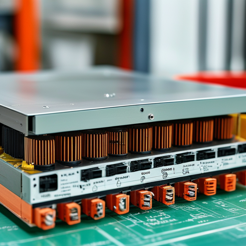
| Profile and Package Height |
Low-profile design
Typical finished heights are approximately 5–15 mm for many compact power-conversion applications, depending on insulation, power level, and cooling requirements.
|
Comparable wire-wound assemblies commonly require approximately 15–40 mm or more, although the actual height depends on the core, bobbin, winding method, and insulation system.
|
A thinner package can support compact products, reduce enclosure volume, and simplify mechanical integration across regional product variants. The approved drawing should define maximum height, mounting tolerances, and insulation barriers.
|
| Operating Frequency |
Commonly applied in high-frequency power converters, often in the approximate range of 100 kHz to 1 MHz. The optimum frequency is determined by core material, switching topology, loss limits, and thermal design.
|
Traditional wire-wound power transformers are also available at high frequency, but winding geometry and leakage control can become more difficult as frequency increases.
|
Supplier capability should include high-frequency loss testing, impedance measurement, thermal validation, and documented control of core material and copper-layer geometry.
|
| Repeatability of Electrical Parameters |
Photolithographic or controlled-layer copper patterns provide consistent winding geometry. Well-controlled designs can achieve repeatable turns ratio, leakage inductance, and interwinding capacitance.
|
Manual or semi-automated winding can show greater variation in wire placement, tension, overlap, and termination unless tightly controlled by fixtures and process inspections.
|
Global suppliers should provide capability data for turns ratio, inductance, leakage inductance, winding resistance, dielectric withstand, and insulation resistance. A first-article report is recommended before volume release.
|
| Thermal Management |
Flat copper layers provide a short thermal path to the core, PCB, or heat-spreading structure. Thermal performance still depends on copper thickness, current density, airflow, and interface materials.
|
Round-wire windings may have less direct contact with heat-spreading surfaces, particularly when multiple insulation layers and winding sections are used.
|
The specification should include temperature-rise limits, test ambient, airflow conditions, hot-spot assumptions, and acceptable thermal-interface materials. Thermal test methods must be identical across candidate suppliers.
|
| Manufacturing Process |
Production may involve multilayer PCB or stamped-copper fabrication, lamination, core assembly, insulation placement, soldering or termination, and electrical testing.
|
Production usually involves wire preparation, winding, insulation application, termination, core assembly, varnishing or potting, and final electrical testing.
|
Planar designs can reduce dependence on specialized winding labor, but they increase reliance on PCB fabrication, copper registration, dielectric quality, and controlled lamination processes.
|
| Material Traceability |
Key materials typically include ferrite or other magnetic cores, copper foil or copper layers, dielectric laminates, solder, insulation films, and bonding materials.
|
Key materials typically include magnetic cores, enamelled copper wire, bobbins, insulation tape, varnish or resin, solder, and termination components.
|
Require lot-level traceability for magnetic material, copper thickness, dielectric system, flame-retardant rating, and insulation components. Material substitutions should require formal engineering approval.
|
| Safety Insulation and Clearance |
Safety performance depends on creepage, clearance, dielectric layer thickness, reinforced-insulation construction, slot geometry, and controlled registration between conductive layers.
|
Safety performance depends on bobbin design, wire insulation, tape systems, margin tape, winding separation, creepage, clearance, and impregnation quality.
|
The design should be evaluated against the applicable end-product and transformer safety requirements, including IEC 62368-1, IEC 61558 series requirements where applicable, and IEC 60664-1 insulation-coordination principles.
|
| Regulatory and Chemical Compliance |
Common compliance considerations include restricted substances in copper, laminate, solder, coatings, adhesives, and flame-retardant materials.
|
Similar obligations apply, with additional attention to wire enamel, varnish, bobbin resin, insulation tape, and potting compounds.
|
Request current RoHS and REACH declarations, material declarations, conflict-minerals information where required by the customer, and evidence for applicable flammability ratings such as UL 94 classifications.
|
| Quality-Control Strategy |
Recommended controls include automated optical inspection, dimensional inspection, copper-pattern verification, layer-registration checks, solder-joint inspection, hipot testing, and inductance or impedance testing.
|
Recommended controls include winding-count verification, wire-tension monitoring, visual inspection, termination checks, hipot testing, inductance testing, and resistance measurement.
|
A supplier-quality agreement should define sampling plans, process capability targets, nonconformance handling, change notification, calibration requirements, and retained-sample policies.
|
| Supply-Chain Risk |
The supply chain may depend on specialized magnetic cores, multilayer fabrication capacity, high-current copper processing, and qualified insulation systems.
|
Wire, bobbin, core, and winding capacity is broadly available, but qualified sources may still be limited for unusual power ratings, insulation classes, or automated production requirements.
|
Dual-source critical cores and insulation materials where practical. Maintain approved alternates for core geometry, laminate construction, plating, and termination methods without changing safety-critical characteristics.
|
| Tooling and Qualification Cost |
Initial costs can include PCB tooling, layer registration studies, custom cores, test fixtures, and thermal prototypes. Unit economics often improve at stable production volumes.
|
Tooling may be lower for standard bobbins and winding equipment, although complex winding, multiple insulation operations, and manual assembly can increase recurring labor costs.
|
Compare total landed cost rather than piece price alone. Include tooling amortization, qualification testing, regulatory documentation, inspection, freight, yield, and the cost of engineering changes.
|
| Lead-Time Planning |
Production lead time is affected by custom PCB fabrication, core availability, lamination capacity, and electrical or thermal qualification.
|
Lead time is affected by bobbin and core availability, winding capacity, insulation operations, and manual or automated assembly queues.
|
Separate prototype, pilot, and mass-production lead times in the quotation. Establish safety stock for long-lead magnetic materials and define approved substitute materials before a shortage occurs.
|
| Design-Change Control |
Small changes in copper width, layer spacing, dielectric thickness, via structure, or core gap can affect electrical performance and safety distances.
|
Changes in wire gauge, winding arrangement, insulation thickness, bobbin dimensions, or core assembly can also affect performance and compliance.
|
Require written notification and requalification for changes to materials, manufacturing location, core geometry, winding structure, insulation system, plating, or critical process parameters.
|
 Xinping