 Xinping
Xinping
Xinping
Choosing the right PFC Inductor begins with the converter’s real operating conditions, not a catalogue headline. Input voltage, switching frequency, output power, ripple current, and thermal limits must work together. A component that looks suitable at room temperature may overheat inside a sealed power supply. That detail is easy to miss.
Robert W. Erickson, a respected power-electronics researcher and co-author of Fundamentals of Power Electronics, described the design goal clearly: “The objective of power factor correction is to make the converter appear as a resistive load to the ac line.” This principle still guides practical PFC Inductor selection. The magnetic core must store energy without saturation. The winding must handle peak current without excessive copper loss. Its inductance must remain stable across temperature and bias.
A useful review should examine more than nominal inductance. Measure current ripple on the bench. Check the temperature rise after continuous full-load operation. Inspect the waveform for ringing, audible noise, and unexpected spikes. Verify the inductor’s saturation rating at the actual peak current, not only at a supplier’s preferred test condition.
Datasheets help. They do not replace testing.
There is also a common design mistake: choosing the smallest inductor to save space. That decision can increase electromagnetic interference, switching stress, and acoustic noise. A larger part is not automatically better either. It may raise cost, resistance, and board area. The right PFC Inductor is a balanced choice, supported by calculations, manufacturer data, and measured evidence. Even experienced engineers should leave room for correction. Real hardware often challenges a perfect spreadsheet.
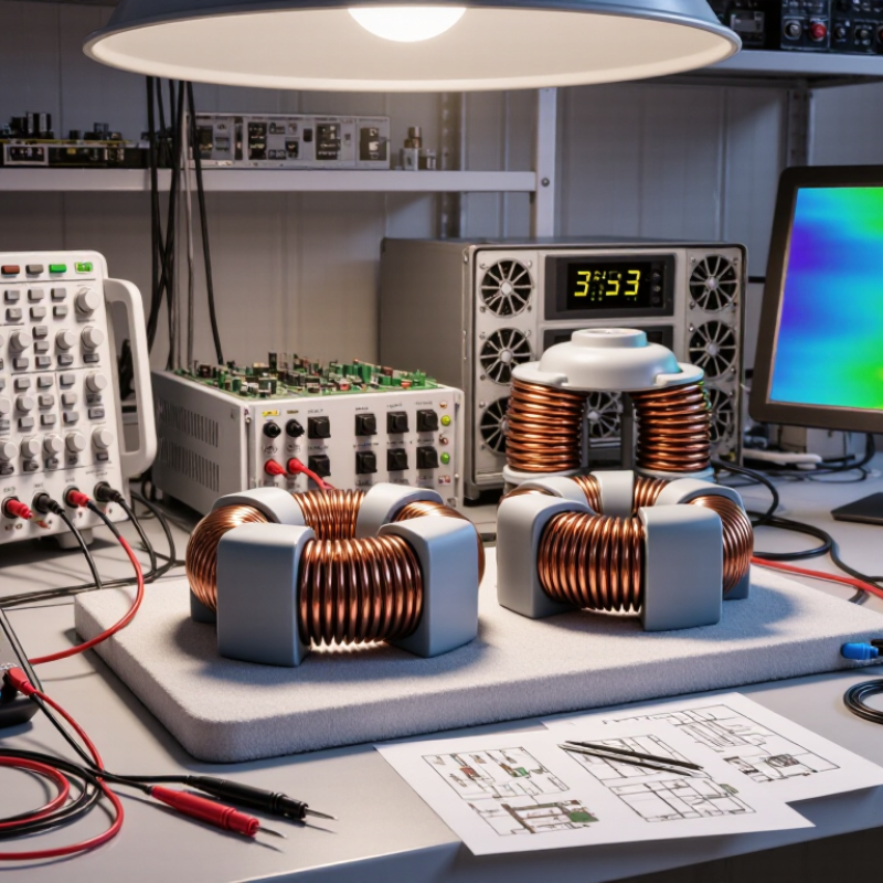
How to Choose the Right PFC Inductor?
Understanding the Role of a PFC Inductor in Power Factor Correction
A PFC inductor shapes the input current so it follows the AC voltage waveform more closely. This reduces reactive current and improves power factor. In an active PFC circuit, the inductor stores energy during each switching cycle. It then releases that energy through the converter. Its value affects ripple current, efficiency, control stability, and electromagnetic interference. A wrong choice can make the circuit noisy or dangerously hot.
Start with input voltage, output power, switching frequency, and permitted ripple current. Higher inductance usually lowers ripple, but it can increase size and slow transient response. Lower inductance may improve response, yet it often creates higher peak current and greater losses. The core must avoid saturation at maximum load, low line voltage, and elevated temperature. Check the saturation curve, not only the nominal inductance.
Thermal design needs equal attention. Copper loss depends on RMS current, while core loss rises with frequency and flux swing. Measure the winding temperature after extended operation. A practical design should also consider creepage, insulation, acoustic noise, and mechanical clearance. Calculations are useful, but they are not enough. The first design is rarely perfect. Test conducted emissions, efficiency, startup behavior, and worst-case current with proper instruments. Recheck the design across tolerance and temperature ranges. That's where hidden weaknesses appear.
| Selection Dimension | Typical Design Data | Why It Matters in PFC | Recommended Selection Guidance | Design Check |
|---|---|---|---|---|
| PFC Topology | Boost PFC; continuous conduction mode (CCM) or critical conduction mode (CrM) | The topology determines the current waveform, switching frequency, inductance requirement, and control strategy. | Use CCM for medium- to high-power applications where low input-current ripple and high efficiency are important. Consider CrM for lower-power designs that can accept variable switching frequency. | Confirm the controller and gate-drive circuit support the selected operating mode. |
| Input Voltage Range | 90–264 VAC, 47–63 Hz for a universal mains input | Inductor current changes with line voltage. Low-line operation generally produces the highest input current and the greatest thermal stress. | Calculate the inductor for the minimum AC input voltage and maximum rated output power. | Check operation at the lowest line voltage, highest load, and minimum switching frequency. |
| Output Voltage | Typically 380–410 VDC for universal-input boost PFC | The boost stage must maintain an output voltage above the peak of the maximum input line. | Select an output-voltage target that provides sufficient control margin without unnecessarily increasing semiconductor and capacitor voltage stress. | For 264 VAC input, the peak line voltage is approximately 373 V, excluding tolerances and transients. |
| Rated Output Power | Example design range: 300–1,000 W | Output power determines average input current, RMS winding current, copper loss, and core temperature rise. | Size the inductor using maximum continuous power plus an appropriate overload and tolerance margin. | Use the worst-case efficiency value rather than nominal efficiency in current calculations. |
| Inductance Value | Common CCM starting range: approximately 200 µH–1.5 mH, depending on power and switching frequency | Higher inductance reduces current ripple but increases physical size and may slow current response. Lower inductance reduces size but increases ripple and peak current. | Choose the value from the required ripple-current ratio, switching frequency, duty cycle, and operating point. | Verify inductance at the actual DC bias current, not only at the small-signal or zero-current rating. |
| Switching Frequency | Typical CCM range: 50–150 kHz | Higher frequency can reduce inductance and magnetic size, but usually increases core loss, winding loss, and EMI concerns. | Select a frequency that balances efficiency, thermal performance, audible noise, component size, and controller capability. | Use the actual switching waveform and maximum temperature when estimating core loss. |
| Ripple Current | Typical design target: 20–40% of the peak or average inductor current, depending on the control method | Ripple current affects peak current, conducted EMI, core loss, and the stress on the switching devices and diode. | Reduce ripple when low EMI and low peak current are priorities; allow more ripple when size and transient response are more important. | Confirm that peak current remains below the controller limit and the magnetic saturation limit. |
| Saturation Current | Preferably at least 20–30% above the calculated maximum peak current | Core saturation causes a sharp reduction in inductance, excessive current rise, higher losses, and possible switch or fuse failure. | Use the maximum low-line, full-load, start-up, overload, and transient current when defining the required saturation-current rating. | Evaluate saturation at the highest expected winding temperature because magnetic performance can change with temperature. |
| RMS Current Rating | Should exceed the calculated RMS winding current with thermal margin | RMS current determines copper loss and contributes directly to the inductor temperature rise. | Choose a part whose temperature rise remains acceptable at the maximum ambient temperature and enclosed-system airflow conditions. | Include ripple current, line-frequency variation, and overload duration in the RMS calculation. |
| Core Material | Common choices include gapped ferrite, powdered iron, and distributed-gap magnetic materials | Core material affects energy storage, permeability, saturation behavior, frequency loss, and temperature stability. | Use a gapped ferrite or distributed-gap structure when controlled inductance and low high-frequency loss are required. Compare material loss data at the intended frequency and flux density. | Do not select a core only by physical size; compare core loss, gap design, and DC-bias performance. |
| Core Loss | Must be calculated from operating frequency, AC flux swing, DC bias, and temperature | Core loss can dominate the thermal performance at high switching frequency or high ripple current. | Use manufacturer-provided magnetic loss curves or validated material models at the real operating conditions. | Keep the calculated core temperature below the material and insulation-system limits. |
| Winding Design | Use adequately sized copper wire, foil, or parallel conductors; consider skin effect above approximately 50–100 kHz | Winding resistance and proximity effect create copper loss and can reduce efficiency. | Balance conductor cross-sectional area, window fill, insulation spacing, and AC resistance. Parallel or litz-style conductors may help at higher frequencies. | Check both DC resistance and AC resistance at the selected switching frequency. |
| Insulation and Isolation | Designed for the applicable mains overvoltage category, working voltage, clearance, and creepage requirements | The PFC inductor is connected to the rectified mains and must withstand normal operating voltage and transient events. | Use suitable insulation materials and construction for the product safety standard and pollution degree of the end equipment. | Verify dielectric withstand, insulation resistance, creepage, clearance, and temperature-class requirements. |
| EMI Performance | Target low differential-mode noise while meeting applicable conducted-emission limits | The inductor filters high-frequency current ripple and influences the input-current waveform and common-mode noise behavior. | Optimize the inductor together with the input EMI filter, layout, switching devices, snubbers, and current-loop area. | Measure conducted emissions using the intended enclosure, cable length, load, and input-line conditions. |
| Efficiency Target | Typical PFC stage target: approximately 95–99%, depending on power level and topology | Inductor copper and core losses directly reduce efficiency and increase thermal stress. | Compare total magnetic loss against the size and cost benefit of a smaller, higher-frequency design. | Measure efficiency at low line, high line, light load, nominal load, and full load. |
| Temperature Rise | Common practical target: below 40–60°C above ambient, subject to system limits | Excessive temperature accelerates insulation aging, shifts magnetic properties, and reduces reliability. | Allow margin below the rated maximum temperature of the wire, bobbin, core, and insulation system. | Test inside the final enclosure with realistic airflow and nearby heat sources. |
| Mechanical Size | Determined by stored energy, current rating, insulation spacing, thermal path, and allowable height | A larger magnetic component can reduce loss and temperature rise but may increase cost and board area. | Choose the smallest part that meets electrical, thermal, safety, and manufacturability requirements with adequate margin. | Check pin spacing, mounting strength, vibration resistance, and clearance from heat-sensitive components. |
| Control-Loop Interaction | Inductor value influences current-loop gain, current-sense waveform, and transient response | An unsuitable inductance can cause control instability, excessive distortion, or slow response to load changes. | Recalculate the compensation network after changing the inductance, switching frequency, or operating mode. | Verify power factor, total harmonic distortion, start-up behavior, and stability across the full input and load range. |
| Reliability Margin | Recommended design margin: 20–30% for current and thermal limits where practical | Component tolerances, aging, line variation, manufacturing differences, and abnormal operating events can increase stress. | Specify tolerances for inductance, saturation current, resistance, temperature rise, and insulation performance. | Perform overload, short-duration surge, repetitive start-up, and high-temperature endurance testing. |
Record input voltage, output power, switching frequency, ripple-current limits, and maximum peak current.
Low-line startup and overload can create brief current surges.
Measure available height, footprint, mounting method, and airflow paths first.
Check core loss, copper loss, winding resistance, ripple current, and skin-effect impact.
Test at minimum input voltage and maximum load.
Inspect winding insulation, creepage, clearance, vibration resistance, and aging information.
Measure inductance at the actual operating current, not only at zero current.
Rounded current peaks can indicate core saturation.
No. A spreadsheet helps, but it cannot reproduce restricted airflow inside a sealed enclosure.
Choosing the right PFC Inductor is essential for improving power factor, reducing harmonic distortion, and supporting stable, efficient power conversion. The selection process should begin by understanding the inductor’s role in the correction circuit and defining the electrical and mechanical requirements of the application. Key factors include the target inductance, peak and RMS current ratings, switching frequency, core material, winding structure, operating voltage, available space, mounting method, and insulation needs. These requirements should be matched carefully with the converter’s operating conditions and expected load range.
A complete evaluation must also consider copper and core losses, temperature rise, cooling conditions, physical size, acoustic behavior, and long-term reliability. The inductor should maintain acceptable performance without excessive saturation or overheating during normal and abnormal operating conditions. Before final approval, engineers should verify its behavior through circuit testing, including efficiency, power factor, current waveform, thermal performance, and transient response. Safety checks, insulation verification, and protection against mechanical or environmental stress are also important to ensure dependable operation throughout the product’s service life.
