
Xinping
A High Frequency Transformer transfers electrical energy at switching frequencies far above the 50 or 60 hertz used in conventional power systems. Its core, windings, insulation, and winding arrangement work together inside a compact magnetic structure. The goal is not simply voltage conversion. Designers also manage isolation, efficiency, heat, electromagnetic interference, and physical size.
Power-electronics author Marian K. Kazimierczuk has noted, “The transformer is one of the most important components in power electronics.” That observation remains practical today. In a laptop adapter, a ferrite core may switch thousands of times per second while carrying energy through tightly controlled windings. Small changes in air gap, wire placement, or switching timing can affect temperature and output stability.
It is a precise device.
This article explains how a High Frequency Transformer works, why ferrite materials are commonly selected, and how magnetic flux moves energy between isolated circuits. It also examines turns ratio, leakage inductance, core loss, copper loss, and insulation requirements. These details often decide whether a design runs quietly or produces unwanted noise.
However, efficiency figures can be misleading. A transformer may perform well in laboratory conditions but lose efficiency inside a crowded enclosure. Real designs face imperfect cooling, manufacturing tolerances, and changing loads. That is where experience matters. Engineers must compare calculations with thermal measurements, waveform testing, and long-term reliability results. The theory is essential, but it does not answer every practical question.
What Is a High Frequency Transformer and How Does It Work?
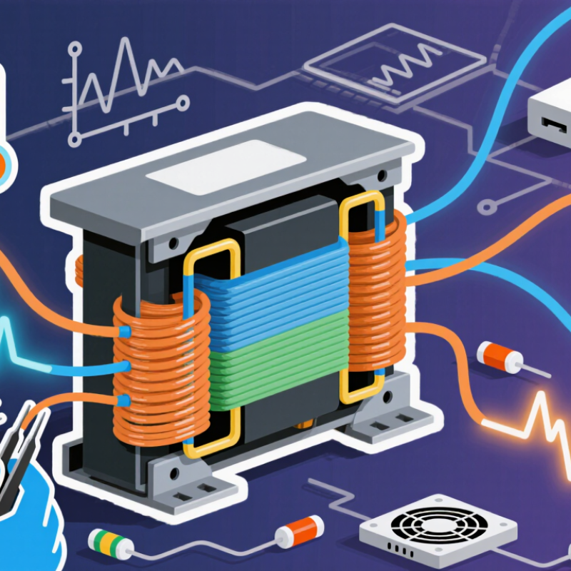
A high-frequency transformer transfers electrical energy between circuits using magnetic coupling. Unlike a mains-frequency transformer, it operates at much higher switching frequencies, often from several kilohertz to hundreds of kilohertz. Its core usually uses ferrite material, which limits energy loss during rapid magnetic changes. Thin insulated wire forms separate windings around the core. The primary winding receives a switching waveform, while the secondary winding delivers a changed voltage.
The operating process is practical but easy to misunderstand. A switching circuit repeatedly energizes and releases the primary winding. This changing current creates a moving magnetic field inside the core. The field induces voltage in the secondary winding without a direct electrical connection. The turns ratio controls the voltage relationship. More secondary turns usually produce higher voltage. Less turns usually produce lower voltage. Insulation, winding layout, core shape, and leakage inductance strongly affect performance. Engineers often check temperature, waveform distortion, and insulation clearance during testing. Small design errors can create audible noise or unexpected heating.
Tips: Keep winding leads short and use suitable insulation. Heat matters. Measure the switching waveform before judging transformer performance. A design may work on paper but fail under load. I have seen compact prototypes pass a no-load test and overheat quickly during continuous operation. That limitation deserves attention, especially when cooling is limited. Ferrite selection also requires care because its losses change with frequency and temperature.
What Is a High Frequency Transformer and How Does It Work?
A high frequency transformer transfers electrical energy between circuits using magnetic induction. Unlike a low-frequency transformer, it operates at much higher switching frequencies. Its core is usually made from ferrite, which limits energy loss during rapid magnetic changes. The core guides magnetic flux through a controlled path. The primary winding receives pulsed voltage, while the secondary winding delivers isolated output voltage.
Each component has a specific job. The primary and secondary windings determine voltage conversion through their turns ratio. Thin insulated wire helps reduce skin-effect losses, although it cannot remove them completely. A bobbin supports the windings and maintains spacing. Insulation layers prevent short circuits between winding sections. Some designs also use an electrostatic shield to reduce unwanted electrical noise. Core shape matters too. Poor assembly can create an air gap, excess heat, or audible vibration. This detail is easy to underestimate.
Tips: Keep winding paths short and evenly distributed. Measure temperature during real load testing, not only at startup. Check insulation distances carefully. A transformer may work electrically yet fail thermally. Designers should also compare calculated losses with measured results, because simplified models can miss leakage inductance and stray capacitance. That comparison may reveal an uncomfortable design flaw early.
What Is a High Frequency Transformer and How Does It Work?
A high-frequency transformer transfers electrical energy through a changing magnetic field. It does not connect the primary and secondary windings directly. Instead, the primary winding creates a rapidly changing flux inside a magnetic core. That flux induces voltage in the secondary winding.
How High-Frequency Energy Transfer Works
When alternating voltage enters the primary winding, current builds a changing magnetic field. According to Faraday’s law, this field produces voltage across the secondary winding. A higher switching frequency allows the transformer to use a smaller core and fewer winding turns. This is why high-frequency transformers appear in compact power supplies and isolated converters.
The winding ratio controls the voltage relationship. More secondary turns usually create a higher output voltage. Core material, air gaps, insulation, and winding layout also affect performance. In practical testing, excessive leakage inductance can cause voltage spikes and unwanted heat. Parasitic capacitance may also transfer noise across the isolation barrier. These effects are easy to underestimate.
Tips: Keep switching edges controlled, and measure temperature during real operating cycles. Use proper insulation distances. A design that works briefly may fail after hours of heat. I have found that careful winding placement often matters as much as the calculated turns ratio. Perfect models are useful, but they do not replace measurements.
A high-frequency transformer transfers energy between electrically isolated circuits by electromagnetic induction. Increasing the switching frequency shortens each energy-transfer cycle, allowing the magnetic core and windings to be made smaller for the same power level.
Relationship shown: Switching period is calculated using T = 1 / f. For example, a 100 kHz switching frequency has a 10 microsecond period.
A high-frequency transformer transfers energy through alternating magnetic flux, usually from tens of kilohertz to several hundred kilohertz. Its electrical behavior depends strongly on frequency, turns ratio, leakage inductance, and winding resistance. The familiar relationship V = 4.44fNAeBmax shows why higher frequency can reduce core size. However, excessive frequency also increases core loss and switching stress.
Ferrite cores commonly operate below about 0.3–0.5 tesla, while practical designs often use lower flux density for thermal margin. According to IEEE Transactions on Power Electronics reviews published in 2022, modern isolated converters frequently operate between 50 and 500 kilohertz. At these frequencies, the skin effect becomes important. Copper current moves toward the conductor surface, raising AC resistance. Litz wire, foil windings, and careful layer spacing can reduce this loss. Small details matter.
Magnetically, leakage inductance limits voltage regulation and creates switching spikes. Interwinding capacitance also transfers common-mode noise across the insulation barrier. The U.S. Department of Energy’s transformer efficiency analysis reports efficiency benchmarks above 98% for many high-performance transformer systems, but high-frequency converters face different loss mechanisms. That comparison needs care. A laboratory result may ignore connectors, cooling airflow, or uneven winding temperature. A first calculation is rarely enough. Engineers should verify core temperature, saturation margin, insulation distance, and measured waveform distortion under real load conditions.
What Is a High Frequency Transformer and How Does It Work?
A high frequency transformer transfers electrical energy between circuits using magnetic induction. It operates at frequencies far above standard mains power. Higher frequency allows a smaller magnetic core and lighter windings. In a switching power supply, semiconductor switches create rapid voltage pulses. The transformer transfers these pulses while providing voltage conversion and electrical isolation.
Common applications include phone chargers, compact adapters, renewable energy inverters, medical equipment, and industrial control systems. Engineers choose the core material, winding structure, and operating frequency together. Ferrite cores usually reduce magnetic losses at high frequencies. However, excessive frequency can increase heating and switching losses. Poor winding placement may also create leakage inductance, ringing, and unwanted electromagnetic noise. These problems often appear during testing, not on paper.
Tips: Keep windings short and tightly coupled. Use insulation with suitable temperature and voltage ratings. Leave space for airflow around warm components. Measure core temperature under real load conditions. A design that works briefly may fail after hours. I have found that layout details matter more than expected. Small gaps, sharp bends, or uneven winding pressure can change performance. Engineers should verify efficiency, regulation, insulation strength, and noise across the full input and load range. Do not trust a single laboratory reading. Real equipment behaves differently.
| Dimension | Typical Information | Why It Matters |
|---|---|---|
| Definition | A high frequency transformer is a magnetic component that transfers electrical energy between isolated circuits using alternating magnetic flux at frequencies substantially higher than utility frequency. | Higher operating frequency allows the magnetic core and windings to be smaller for a given power level, although high-frequency losses become more important. |
| Operating Frequency | Common designs operate from several kilohertz to hundreds of kilohertz. Some specialized converters operate into the low-megahertz range. | The selected frequency affects core material, winding construction, switching losses, electromagnetic interference, and thermal performance. |
| Working Principle | A switching circuit applies a changing voltage to the primary winding. The resulting alternating flux in the core induces a voltage in the secondary winding according to Faraday’s law. | The transformer can provide voltage conversion, galvanic isolation, impedance transformation, or a combination of these functions. |
| Voltage Ratio | For an ideal transformer, the voltage ratio is approximately proportional to the turns ratio: Vs/Vp ≈ Ns/Np. | The turns ratio is selected to step voltage up or down while maintaining the required isolation and load-current capability. |
| Core Materials | Ferrites are widely used for switching frequencies from tens of kilohertz to several hundred kilohertz. Powdered iron and other magnetic materials may be used for different frequency and energy-storage requirements. | Material selection determines permeability, saturation behavior, core loss, temperature stability, and usable frequency range. |
| Core Loss | Core loss consists primarily of hysteresis and eddy-current loss. It generally increases with frequency and magnetic flux density. | Excessive core loss produces heat, reduces efficiency, and may cause thermal runaway if cooling is inadequate. |
| Winding Loss | Copper loss includes DC resistance loss and frequency-dependent AC loss caused by skin effect and proximity effect. | At high frequency, litz wire, parallel conductors, foil, or carefully arranged PCB windings can reduce current-crowding losses. |
| Magnetic Flux Density | Designers choose a peak flux density below the core’s saturation limit. The safe value depends on core material, frequency, temperature, waveform, and allowable loss. | Operating too close to saturation can cause a sharp increase in magnetizing current, switch stress, distortion, and heating. |
| Isolation | Primary-to-secondary insulation may include reinforced or basic insulation, depending on the required safety standard and system voltage. | Creepage, clearance, insulation thickness, winding margins, and hipot withstand requirements must be considered together. |
| Leakage Inductance | Leakage inductance is the portion of winding inductance linked with one winding but not the other. It is affected by winding spacing, arrangement, and geometry. | It can create voltage spikes and ringing, but in resonant converters it may also be intentionally used as part of the resonant network. |
| Parasitic Capacitance | Interwinding and intrawinding capacitance results from electric fields between conductors and between windings. | Parasitic capacitance can increase common-mode noise, limit high-frequency performance, and affect switching waveforms. |
| Common Topologies | Flyback, forward, push-pull, half-bridge, full-bridge, and resonant converter topologies commonly use high-frequency transformers. | Topology affects transformer excitation, reset requirements, switch voltage stress, power range, efficiency, and control complexity. |
| Power Conversion | High-frequency transformers are used in isolated AC-DC supplies, DC-DC converters, auxiliary power supplies, and charger circuits. | They enable compact, efficient conversion while separating hazardous input circuits from accessible output circuits. |
| Common Applications | Applications include telecommunications power supplies, industrial control equipment, renewable-energy converters, LED drivers, electric-vehicle auxiliary converters, medical power supplies, and consumer electronics. | Compact isolation and voltage conversion are valuable wherever space, efficiency, safety, or regulated output power is important. |
| Efficiency Target | Well-designed transformer stages can achieve high efficiency, but the actual result depends on frequency, load, core loss, winding loss, switching loss, and cooling. | Efficiency must be evaluated across the complete operating range rather than at only one nominal load point. |
| Thermal Design | Thermal design considers core and copper losses, ambient temperature, permissible temperature rise, airflow, enclosure size, and mounting conditions. | Temperature affects resistance, magnetic properties, insulation life, reliability, and the maximum continuous power rating. |
| Electromagnetic Compatibility | Fast switching edges, leakage inductance, parasitic capacitance, and layout loops can generate conducted and radiated emissions. | Shielding, controlled dv/dt, minimized loop area, filtering, proper grounding, and optimized winding layout help control interference. |
| Design Trade-Off | Increasing frequency can reduce transformer size, but may increase core loss, AC winding loss, switching loss, insulation difficulty, and EMI. | The best operating point balances size, cost, efficiency, thermal performance, safety, manufacturability, and compliance requirements. |
| Key Design Checks | Verify turns ratio, volt-second balance, peak flux density, winding current density, core and copper loss, insulation distances, leakage inductance, temperature rise, mechanical construction, and conducted or radiated emissions. | A complete set of checks reduces the risk of saturation, overheating, insulation failure, unstable operation, excessive noise, and premature component failure. |
It transfers electrical energy through a changing magnetic field. The windings remain electrically separated.
Switching voltage creates changing magnetic flux in the core. This flux induces voltage in the secondary winding. No direct connection is required.
Higher frequency allows fewer winding turns and a smaller magnetic core. The result is often lighter and more compact.
More secondary turns usually produce a higher output voltage. However, losses and operating conditions can change the actual result.
Core material, air gaps, insulation, and winding placement all matter. Ferrite materials commonly suit high-frequency operation. Small layout changes can matter.
Leakage inductance may cause voltage spikes, ringing, and extra heat. Parasitic capacitance can transfer unwanted noise across the isolation barrier.
Measure temperature during real operating cycles. Check efficiency, voltage regulation, insulation strength, and noise across input and load ranges.
A design may work briefly, then overheat after several hours. One laboratory reading is not enough. Real equipment behaves differently.
A High Frequency Transformer is a specialized magnetic component designed to transfer electrical energy between circuits at frequencies much higher than those used in conventional power transformers. By operating at high frequency, it can achieve efficient voltage conversion with smaller magnetic cores, reduced winding size, and improved power density. Its main parts include a magnetic core, primary and secondary windings, insulation materials, and protective structural elements. Each component contributes to energy transfer, electrical isolation, heat control, and reliable operation.
During operation, alternating current in the primary winding creates a changing magnetic field in the core, which induces a corresponding voltage in the secondary winding. The turns ratio determines whether the voltage is increased or decreased, while core material, switching frequency, winding arrangement, and insulation affect efficiency and performance. Important design considerations include magnetic losses, copper losses, leakage inductance, electromagnetic interference, thermal management, and safety clearances. High Frequency Transformer designs are widely used in power supplies, renewable energy systems, communication equipment, industrial controls, and other compact electronic applications.
